Technology / OLED fundamentals / Guide 01
OLED Device Architecture and Exciton Formation
From Charge Injection to Light Emission: A Mechanistic and Measurement-Oriented Guide
A connected account of the electrical, excited-state and optical processes that determine how an OLED turns injected charge into externally detected light.
Abstract
Device performance is a chain, not a single property
Organic light-emitting diodes (OLEDs) convert electrical energy into light through a coupled sequence of charge injection, carrier transport, electron–hole recombination, excited-state formation and evolution, radiative decay, and optical outcoupling. Device efficiency therefore cannot be predicted from a single molecular descriptor. This guide connects the physical processes across the device stack, clarifies the assumptions behind the commonly cited 1:3 singlet-to-triplet formation ratio, and distinguishes exciton formation from subsequent spin conversion, energy transfer, radiative decay, and photon escape.
It presents a convention-dependent factorization of external quantum efficiency (EQE), explains why its factors must be defined without double counting, and outlines experimental approaches for testing proposed mechanisms. Particular attention is given to thermally activated delayed fluorescence (TADF), competing excited-state pathways, efficiency roll-off, and operational stability. Conceptual diagrams and equations are intended as explanatory models rather than universal quantitative descriptions; device-specific conclusions require measurements and explicitly stated assumptions.
Scope and status. This manuscript is an explanatory technical guide, not a report of new experimental data. The diagrams and equations are conceptual unless stated otherwise. Before external publication, remaining full-source checks and all figure artwork should receive final scientific review.
01 / Framework
How to read an OLED
An OLED converts electrical work into optical emission through several distinct but coupled events: carriers are injected from electrodes, transported through organic layers, brought into recombination, and converted into excited states. Those states may transfer energy, interconvert between spin manifolds, emit photons, or decay nonradiatively. Photons generated inside the device must then escape the optical structure to contribute to external emission. No single molecular parameter describes this entire sequence.
The early double-layer OLED reported by Tang and VanSlyke demonstrated the importance of separating carrier-transport functions between organic films. Modern OLEDs commonly use more elaborate stacks to control injection, transport, recombination-zone location, exciton confinement, and optical behavior. The appropriate architecture depends on the emitter system, fabrication process, target color, drive conditions, and lifetime requirements. [1]
Learning objectives
- Identify the roles and limitations of electrodes and charge-management layers.
- Distinguish carrier recombination, exciton formation, energy transfer, spin conversion, radiative decay, and optical outcoupling.
- Interpret the 1:3 singlet-to-triplet ratio as a conditional statistical baseline rather than a universal measured branching ratio.
- Understand how the definitions of IQE and EQE depend on the chosen accounting boundary and measurement convention.
- Match common OLED measurements to the physical questions they can—and cannot—answer.
02 / Device stack
Multilayer device architecture
A representative bottom-emitting OLED may contain a transparent substrate and anode, hole-injection and hole-transport layers, an emissive layer (EML), electron-transport and electron-injection layers, and a cathode. Optional hole- or electron-blocking layers may reduce carrier leakage or limit exciton migration toward quenching interfaces. The functions can be combined, omitted, inverted, repeated, or arranged differently in top-emitting and tandem architectures. [2]
The anode generally supplies holes and the cathode electrons under forward bias. HIL/HTL and EIL/ETL layers can improve injection and transport, but functional names do not imply perfect selectivity: many organic materials transport both carrier types to some extent. Interfaces can also introduce energetic offsets, dipoles, traps, and charge accumulation. A device report should therefore state the actual layer sequence, thicknesses, material identities, and doping fractions rather than relying on a generic stack diagram. [2]
03 / Electrical pathway
Charge injection, transport, and recombination
Hole injection is often discussed using occupied molecular levels, commonly described by HOMO energies, while electron injection is discussed using unoccupied levels, commonly described by LUMO energies. These labels are useful but incomplete predictors of injection barriers. Interfacial dipoles, polarization, molecular packing, energetic disorder, electric field, chemical doping, and charge accumulation can change the effective injection and transport behavior. [3]
Once injected, carriers move through organic films whose degree of order and energetic disorder varies by material and processing conditions. Electron and hole mobilities need not be equal, and traps can alter carrier distributions. Nominally symmetric electrode work functions or similar tabulated energy levels do not guarantee balanced carrier supply. The recombination zone is a device-level outcome that depends on the full stack, drive conditions, transport, trapping, and interfacial processes. [3]
Carrier recombination is not synonymous with photon emission. Recombination can populate an excited state on the emitter, on a host, or in an interfacial or charge-transfer configuration. Subsequent energy transfer or charge-transfer-mediated processes may populate the emissive species. The location and width of the recombination zone affect interfacial quenching, exciton–polaron encounters, local exciton density, and coupling to optical modes; a layer diagram alone cannot establish this profile.
04 / Excited-state processes
Exciton formation and competing pathways
In organic semiconductors, excited states often have substantial molecular character, although localization and charge-transfer character can vary. For mechanistic clarity, at least five events should be distinguished: carrier recombination and formation of an excited configuration; spin conversion such as intersystem crossing (ISC) or reverse intersystem crossing (RISC); energy transfer between species; radiative or nonradiative decay; and optical escape of any generated photon. These events may be coupled, and their relative importance depends on the material system and operating conditions.
Energy transfer is not a single mechanism
Förster resonance energy transfer (FRET) is a Coulombic dipole–dipole interaction whose efficiency depends on donor-emission/acceptor-absorption spectral overlap, donor emission yield and lifetime, donor–acceptor separation, and transition-dipole orientation. [4] Dexter transfer instead relies on short-range electron exchange and therefore requires sufficient wavefunction overlap; it is a common route for triplet–triplet transfer. [5] An accessible OLED-focused review supports the detailed distance, overlap and competing-pathway context used here. [6] In host–guest OLEDs, the dominant channel further depends on the spin character of the participating states, their relative energies, morphology, and competing rates. Singlet–singlet FRET can promote fluorescent emission, whereas triplet–triplet Dexter transfer can be useful for phosphorescent guests or detrimental when it populates a quenching triplet on a fluorescent terminal emitter. [6] [7] A calculated or measured transfer rate must be evaluated relative to other pathways from the same initial state.
Host–guest transfer between closed-shell species: the spin constraint
For a conventional closed-shell host H and guest G, both ground states are usually singlets. A host singlet excitation can be transferred to a guest singlet excitation, H(S1) + G(S0) → H(S0) + G(S1), without changing the total spin of the pair. Likewise, H(T1) + G(S0) → H(S0) + G(T1) preserves triplet total-spin character. The first channel is commonly mediated by Förster-type coupling when the relevant optical transitions are allowed; the second is commonly associated with exchange-mediated Dexter transfer. These labels describe typical coupling channels, not a universal exclusion of alternative mechanisms. [4] [5] [6]
In contrast, the crossed channels H(S1) + G(S0) → H(S0) + G(T1) and H(T1) + G(S0) → H(S0) + G(S1) would change the total spin of the isolated closed-shell donor–acceptor pair. Their first-order matrix elements vanish for a spin-conserving interaction. Spin–orbit coupling, mixed charge-transfer configurations, and related state mixing can relax this selection rule, so “spin-forbidden” means strongly suppressed in the idealized limit, not impossible under all conditions. The distinction between a spin-allowed channel and an efficient device-level process remains essential. [8]
Open-shell radical guests: doublet-coupled transfer
An organic radical introduces an unpaired electron and doublet ground/excited states, denoted R(D0) and R(D1). For a closed-shell host donating to a radical guest, H(S1) + R(D0) → H(S0) + R(D1) preserves the overall doublet spin and may proceed by Förster-type transfer when the donor and radical optical transitions couple. The triplet-originating channel H(T1) + R(D0) → H(S0) + R(D1) can also conserve total spin through its doublet-coupled component, commonly via exchange-mediated transfer. The spin coupling is 1 ⊗ 1/2 = 1/2 ⊕ 3/2: a donor triplet and radical ground-state doublet produce total-spin doublet and quartet sectors. Only the appropriately coupled doublet component connects directly to a final doublet product through a strictly spin-conserving transfer channel; the quartet component is not automatically allowed. Li and co-workers provided direct OLED-relevant evidence for singlet- and triplet-originating transfer from the TADF donor 4CzIPN to an emissive TTM-3PCz radical guest. [8]
For the reverse direction, an excited radical donor can in principle sensitize a closed-shell acceptor. R(D1) + G(S0) → R(D0) + G(S1) maintains doublet total spin, while R(D1) + G(S0) → R(D0) + G(T1) has a spin-conserving route only into the doublet-coupled component of the radical-ground-state/guest-triplet product, not automatically the quartet component. This establishes theoretical spin compatibility, not a general experimental demonstration of efficient reverse transfer. Li et al. experimentally tested the opposite, closed-shell-donor-to-radical-guest direction and did not directly verify every reverse-transfer process. Related covalently linked radical–anthracene systems studied by Gorgon et al. exhibit coupled triplet-character and high-spin states, but they are not universal proof of efficient intermolecular transfer. [8] [9]
On smaller screens, scroll horizontally to inspect the complete diagram.
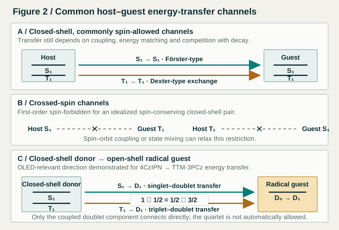
Thus, three questions should be answered separately: Is the proposed pair-state transition compatible with total-spin selection? Is there a physically viable electronic coupling mechanism, such as dipole–dipole, exchange, or charge-transfer-mediated coupling? And is the transfer rate fast enough to compete with radiative decay, quenching, and other device processes? A relaxed spin restriction is not a guarantee of “free” or efficient energy transfer.
Charge-transfer states may act as intermediates in excitation formation or transfer, but they can also provide nonradiative loss channels. Their role should be established from evidence appropriate to the system, rather than inferred solely from a simplified energy-level diagram. [6]
A minimal kinetic picture
For an illustrative singlet population [S1], one may write:
Here GS is an effective singlet-generation term; kRISC is the reverse intersystem-crossing rate; kr,S and knr,S are the singlet radiative and nonradiative decay rates; and kISC is the intersystem-crossing rate. This equation is deliberately incomplete: a full model may require triplet generation and decay, host–guest transfer, additional excited states, annihilation terms, charge-dependent effects, and time- or density-dependent coefficients. Its purpose is to emphasize that a pathway must be interpreted alongside its competitors. [10]
05 / Spin statistics
Singlet and triplet excitons: what the 1:3 ratio means
In an idealized spin-statistical model, two independently injected, unpolarized spin-½ carriers can combine into one total-spin singlet configuration and three triplet substates. If the accessible configurations form with equal statistical weight, the initial exciton-formation fractions are approximately 25% singlet and 75% triplet. This is a useful baseline for understanding why a simple prompt-fluorescent emitter may not use all triplet-originating excitations. [7] [11]
This ratio is a model assumption, not a universal experimentally measured branching ratio. Formation kinetics, charge-transfer states, spin-dependent processes, and the specific recombination mechanism can affect the observed populations. More importantly, initial spin populations are not the same as the final fractions of excitations that produce useful photons. ISC, RISC, triplet–triplet annihilation (TTA), energy transfer, nonradiative decay, and quenching can change how excitation energy is used after formation. [7] [11]
The often-quoted 25% limit applies only to an idealized prompt-fluorescence route that does not harvest or convert triplet excitations, and it should not be treated as a universal OLED IQE or EQE limit. TADF, phosphorescence, TTA-assisted fluorescence, and other exciton-management strategies can alter the use of triplet-originating excitations, although their efficiencies and practical limitations differ. [7]
06 / Photophysics
Radiative pathways and TADF
Fluorescence usually denotes a radiative transition between states of the same spin multiplicity, commonly S1 → S0. Phosphorescence involves a change in spin multiplicity, commonly T1 → S0. In purely organic molecules, phosphorescence is often weak because the transition is spin-forbidden to a first approximation; stronger spin–orbit coupling, including that associated with suitable heavy-metal complexes, can increase its probability. [7] [11]
Thermally activated delayed fluorescence uses RISC to return triplet population to an emissive singlet manifold, followed by fluorescence. A small singlet–triplet energy gap ΔEST can be beneficial, but it does not alone determine the RISC rate. The electronic character of the participating states, vibronic coupling, spin–orbit coupling, the availability of intermediate states, and competing decay pathways can all matter. Consequently, neither ΔEST nor a single photoluminescence lifetime should be used alone to infer device efficiency. [10] [12]
Distinguishing delayed-fluorescence mechanisms
Delayed emission is not unique to TADF. TTA can also produce delayed fluorescence, and multiple mechanisms may coexist. Mechanistic assignments should therefore draw on complementary evidence where appropriate: time-resolved photoluminescence, temperature dependence, excitation-density dependence, oxygen sensitivity, transient absorption, and comparison between optical and electrical excitation. Each method has limitations; for example, temperature dependence is not uniquely diagnostic of RISC, and a decay curve alone rarely identifies every rate process. [10] [12]
Nonradiative pathways include internal conversion, vibrationally assisted relaxation, impurity or interface quenching, exciton–exciton annihilation, and exciton–polaron annihilation. Photoluminescence under optical excitation can characterize selected excited-state processes, but it cannot by itself quantify charge imbalance or all spin-conversion and quenching processes under electrical operation. [10]
07 / Device metrics
From internal photon generation to EQE
External quantum efficiency (EQE) is the number of photons emitted into the defined external measurement domain per electron passing through the device. The measured value depends on calibration, collection geometry, and the stated measurement convention. A useful illustrative factorization is: [2]
| Factor | Illustrative meaning | Definition that must be stated |
|---|---|---|
| γ | Fraction of injected electron–hole pairs that forms excitations in the defined active system | How leakage, failed recombination, and charge imbalance are treated |
| ηexc | Fraction of those excitations that reaches the defined emitting-state ensemble | Whether spin conversion and host–guest transfer are included, and at what boundary |
| Φeff | Conditional probability that an excitation in that ensemble produces an internal photon | Which radiative/nonradiative processes and density-dependent losses are included |
| ηout | Fraction of internally generated photons that reaches the defined external measurement domain | Optical stack, dipole orientation, collection geometry, and calibration convention |
This is an accounting framework, not a unique decomposition that can always be measured factor by factor. Each term must be defined by the author for the system under study, and the chosen boundaries must prevent losses or transfer events from being counted twice. [2]
Under this convention, IQE is represented by the product of the first three factors and EQE = IQE × ηout. Other publications may place spin conversion, energy transfer, or charge balance in differently named terms. Comparisons are meaningful only when the definitions are aligned. In real devices, the factors may be coupled and condition-dependent; they should not be presented as independently measured quantities unless the methods support that claim. [2]
Conceptually, IQE counts internally generated photons per injected electron, whereas EQE counts photons reaching the defined external measurement domain per injected electron. High IQE does not guarantee equally high EQE: reflection, absorption, substrate-guided modes, waveguiding, plasmonic losses, and optical interference can limit outcoupling. Layer thicknesses, refractive indices, emitter orientation, and cavity effects can change the external emission. EQE is therefore a device-level result, not an intrinsic score for an isolated molecule. [2] [13]
08 / Measurement logic
How to test proposed mechanisms
No single measurement can uniquely determine every contribution to OLED performance. A credible mechanistic argument should combine measurements that address different parts of the process and state what each method cannot establish. [10]
| Method | Useful question | Important limitation |
|---|---|---|
| Steady-state PL and PLQY | How efficiently does the sample emit under optical excitation? | Does not directly measure charge injection, charge balance, or all device losses. |
| Time-resolved PL | What decay timescales and delayed components are present? | Decay components are not automatically unique signatures of specific mechanisms. |
| Temperature-dependent PL | Does the photophysics show thermally activated behavior? | Temperature dependence alone does not prove TADF or uniquely determine kRISC. |
| Excitation-density dependence | Are bimolecular processes such as TTA plausible? | Other density-dependent effects can complicate interpretation. |
| Transient absorption | Are transient states or triplet-associated signatures observable? | State assignment and quantitative extraction may require a model. |
| EL spectra and current-dependent EQE | How does the device emit under electrical operation, and how does efficiency change with drive? | Does not by itself separate all internal loss channels. |
| Optical modelling and orientation analysis | How might the stack and transition-dipole orientation affect outcoupling? | Depends on reliable optical constants, stack geometry, and model assumptions. |
| Lifetime testing and post-mortem analysis | How does performance evolve under defined operating stress? | Results are comparable only when stress conditions and endpoints are stated. |
A literature-based case study would strengthen this guide. It should use one published device with traceable data and report the stack, layer thicknesses, emissive composition, relevant photophysical measurements, EQE versus luminance or current density, measurement geometry, and lifetime conditions where available. Values should not be transplanted from unrelated devices or presented without their original conditions. [10] [14]
09 / Design practice
Material and device engineering decisions
OLED engineering requires balancing coupled design variables rather than maximizing isolated material parameters. Injection barriers and carrier mobilities shape carrier distributions; host and guest excited-state energies affect energy transfer and confinement; concentration and morphology influence transfer, aggregation, and quenching; and the optical stack determines how internal emission is extracted. Device reliability additionally depends on chemical stability, interfaces, processing, and the stress conditions under which the device operates. [2] [3] [6]
- Injection: evaluate electrode contacts, interfacial processing, and injection layers rather than relying only on tabulated HOMO/LUMO values. [3]
- Recombination: determine or constrain the likely recombination-zone position and width; distinguish direct measurement from inference.
- Exciton management: consider singlet and triplet energies, host–guest transfer, spin conversion, confinement, and annihilation channels. [6]
- Optics: report layer thicknesses, optical constants, measurement geometry, and emitter-orientation assumptions when comparing EQE. [2]
- Efficiency roll-off: investigate exciton-density-dependent annihilation, charge imbalance, and heating as possible contributors rather than assigning one universal cause. [14]
- Reliability: compare lifetime values only when initial luminance or current density, endpoint such as LT95 or LT50, environment, and testing protocol are specified. [15]
- Manufacturing: consider purity, process compatibility, reproducibility, device yield, and durability in addition to proof-of-principle efficiency.
10 / Operating conditions
Efficiency, efficiency roll-off, and operational stability
Peak EQE is not equivalent to efficiency under practical operating conditions. A device may show a high maximum value but lose efficiency as current density or luminance increases. Potential contributors include exciton–exciton annihilation, exciton–polaron annihilation, changing charge balance, and heating. The dominant mechanism depends on the device and should be tested rather than assumed. [14] [10]
High efficiency also does not necessarily imply long operational lifetime. Degradation may involve chemically and physically distinct pathways, including excited-state-induced reactions, charge accumulation, interfacial changes, morphological evolution, and material-specific bond instability. These processes are especially important in demanding color regimes such as blue emission, but no single mechanism applies to every device. [15]
Meaningful device comparisons should report at minimum the stack and emissive composition; EL spectrum; peak EQE and EQE at a stated luminance; current–voltage–luminance behavior; measurement geometry and calibration; and lifetime endpoint under specified stress conditions. Missing evidence should remain explicitly identified rather than converted into an apparently precise ranking. [14] [15]
11 / Interpretive safeguards
Limitations and open questions
This guide intentionally avoids presenting universal numerical values for energy levels, transfer rates, mobilities, or layer thicknesses because these depend on the selected materials and architecture. The diagrams are conceptual and the kinetic equation is illustrative, not a complete model for every OLED. A device-specific analysis should define its state network, specify the assumptions behind its efficiency accounting, and use measurements suited to the mechanisms being claimed. [14] [15]
Several questions remain system-dependent: how the recombination zone changes with drive; when a host–guest transfer pathway outcompetes spin conversion or quenching; which processes dominate efficiency roll-off; how emitter orientation interacts with cavity effects; and how the same excited-state chemistry influences both efficiency and degradation. Addressing these questions generally requires complementary optical, electrical, structural, and computational evidence. [14] [6]
12 / Synthesis
Conclusions
OLED performance emerges from a chain of coupled electrical, excited-state, and optical processes. The 1:3 singlet-to-triplet ratio is a useful conditional baseline, not a universal device limit. TADF can enable triplet-originating excitations to contribute to fluorescence, but its performance depends on more than ΔEST. Likewise, energy-transfer rates, photoluminescence yields, and molecular descriptors must be interpreted in the context of competing pathways and the full device architecture. [11] [12] [14] Open-shell radical emitters additionally enable doublet-coupled energy-transfer routes, but their spin-allowed components and competition with loss pathways must be established for the specific system. [8] [9]
The most reliable OLED analysis makes definitions explicit, separates observations from mechanistic inference, compares competing rates on a consistent basis, and reports measurement conditions transparently. A conceptual framework is most useful when it guides experiments without implying more certainty than the evidence supports.
13 / Provenance
References and source-verification notes
References [1]–[15] are numbered in the order of their first appearance in this web revision. Verification denotes the scope of source material actually inspected for claims used in this guide. It does not imply that all experimental data in every paper have been independently reproduced, nor that all sources received a full-text check. The detailed source-to-claim audit is linked from the editorial review record.
C. W. Tang and S. A. VanSlyke. “Organic electroluminescent diodes.” Applied Physics Letters 51, 913–915 (1987). DOI: 10.1063/1.98799
FULL TEXT: Original three-page paper inspected for bilayer architecture and recombination; broader interpretation remains contextual.
F. Tenopala-Carmona et al.. “Identification of the Key Parameters for Horizontal Transition Dipole Orientation in Fluorescent and TADF Organic Light-Emitting Diodes.” Advanced Materials 33, 2100677 (2021). DOI: 10.1002/adma.202100677
FULL TEXT: Open manuscript checked for TDM orientation and OLED optical outcoupling.
P. Li and Z.-H. Lu. “Interface Engineering in Organic Electronics: Energy-Level Alignment and Charge Transport.” Small Science 1, 2000015 (2021). DOI: 10.1002/smsc.202000015
FULL TEXT: Open PMC version checked for electrode–organic interfaces, energy-level alignment, injection barriers, interface dipoles, disorder and hopping transport.
T. Förster. “Zwischenmolekulare Energiewanderung und Fluoreszenz.” Annalen der Physik 437, 55–75 (1948). DOI: 10.1002/andp.19484370105
ABSTRACT / METADATA: Publisher abstract and bibliographic record checked; original full text remains unverified, so detailed mechanism claims are also mapped to reference [6].
D. L. Dexter. “A Theory of Sensitized Luminescence in Solids.” The Journal of Chemical Physics 21, 836–850 (1953). DOI: 10.1063/1.1699044
ABSTRACT / METADATA: Publisher abstract and bibliographic record checked; original full text remains unverified, so OLED-specific interpretation is also mapped to reference [6].
U. Deori, G. P. Nanda, C. Murawski and P. Rajamalli. “A perspective on next-generation hyperfluorescent organic light-emitting diodes.” Chemical Science 15, 17739–17759 (2024). DOI: 10.1039/D4SC05489J
FULL TEXT: Open PMC article checked for host–guest FRET/Dexter roles, distance dependence and competing pathways.
H. Nakanotani et al.. “High-efficiency organic light-emitting diodes with fluorescent emitters.” Nature Communications 5, 4016 (2014). DOI: 10.1038/ncomms5016
FULL TEXT: Complete publisher PDF checked for spin statistics, EQE accounting, TADF assistance and cascade energy transfer.
F. Li, A. J. Gillett, Q. Gu, J. Ding, Z. Chen, T. J. H. Hele, W. K. Myers, R. H. Friend and E. W. Evans. “Singlet and triplet to doublet energy transfer: improving organic light-emitting diodes with radicals.” Nature Communications 13, 2744 (2022). DOI: 10.1038/s41467-022-29759-7
FULL TEXT: Open publisher PDF checked for 4CzIPN singlet/triplet to TTM-3PCz doublet transfer, pair-spin discussion and OLED evidence.
S. Gorgon et al.. “Reversible spin-optical interface in luminescent organic radicals.” Nature 620, 538–544 (2023). DOI: 10.1038/s41586-023-06222-1
FULL TEXT: Open PMC article checked for covalently coupled radical–anthracene triplet-character and high-spin states; it is not treated as universal intermolecular-transfer proof.
M. Hasan et al.. “Probing polaron-induced exciton quenching in TADF based organic light-emitting diodes.” Nature Communications 13, 254 (2022). DOI: 10.1038/s41467-021-27739-x
FULL TEXT: Open publisher article checked for singlet/triplet rate equations, annihilation and efficiency roll-off.
M. A. Baldo et al.. “Highly efficient phosphorescent emission from organic electroluminescent devices.” Nature 395, 151–154 (1998). DOI: 10.1038/25954
ABSTRACT / METADATA: Publisher abstract and bibliographic record checked; complete original article remains unverified and the claim mapping is limited accordingly.
H. Uoyama, K. Goushi, K. Shizu, H. Nomura and C. Adachi. “Highly efficient organic light-emitting diodes from delayed fluorescence.” Nature 492, 234–238 (2012). DOI: 10.1038/nature11687
ABSTRACT / METADATA: Publisher and institutional abstract/metadata checked; original full-text claim-by-claim audit remains open.
Y. Zhang and R. Biswas. “High Light Outcoupling Efficiency from Periodically Corrugated OLEDs.” ACS Omega 6, 9291–9301 (2021). DOI: 10.1021/acsomega.1c00903
FULL TEXT: Open ACS/PMC article checked for optical modes, plasmonic loss and outcoupling modelling.
S. Diesing, L. Zhang, E. Zysman-Colman and I. D. W. Samuel. “A figure of merit for efficiency roll-off in TADF-based organic LEDs.” Nature 627, 747–753 (2024). DOI: 10.1038/s41586-024-07149-x
FULL TEXT: Open Nature/PMC article inspected for TADF kinetics, annihilation and roll-off design arguments.
E. Tankelevičiūtė, I. D. W. Samuel and E. Zysman-Colman. “The Blue Problem: OLED Stability and Degradation Mechanisms.” The Journal of Physical Chemistry Letters 15, 1034–1047 (2024). DOI: 10.1021/acs.jpclett.3c03317
FULL TEXT: Open PMC and institutional-repository versions checked for blue OLED degradation, reliability and reporting caveats.