Abstract
Hyperfluorescence (HF) combines triplet harvesting by a sensitizer with spectrally selective fluorescence from a separate terminal emitter. Desired sensitizer-singlet to terminal-singlet Förster transfer (FRET) competes with Dexter-type triplet exchange, direct charge capture, annihilation and chemical degradation. This mechanism-first review distinguishes molecule, film and complete-device evidence; uses a bounded four-population kinetic model and a conditional ISC/RISC/FRET branching calculation; and assesses quadrupolar sensitizers, covalently encapsulated terminal emitters, single-layer systems and tandem OLEDs. Encapsulation can suppress Dexter transfer while reducing FRET. We additionally distinguish reported EQEs from optical-angle-corrected EQEs where the original source publishes both. Reported optical properties, model-inferred rates, efficiency at defined luminance and operational lifetime remain separate evidence domains. This is an educational critical review, not an original experimental study.
Learning objectives
Distinguish a sensitizer RISC mechanism from terminal fluorescence; evaluate FRET and Dexter exchange without comparing arbitrarily normalized curves; understand the assumptions in effective-rate and repeated ISC/RISC models; identify molecular shielding trade-offs; separate PL and EL FWHM; and interpret EQE, roll-off and lifetime within matched device protocols.
1. Why hyperfluorescence is a device architecture
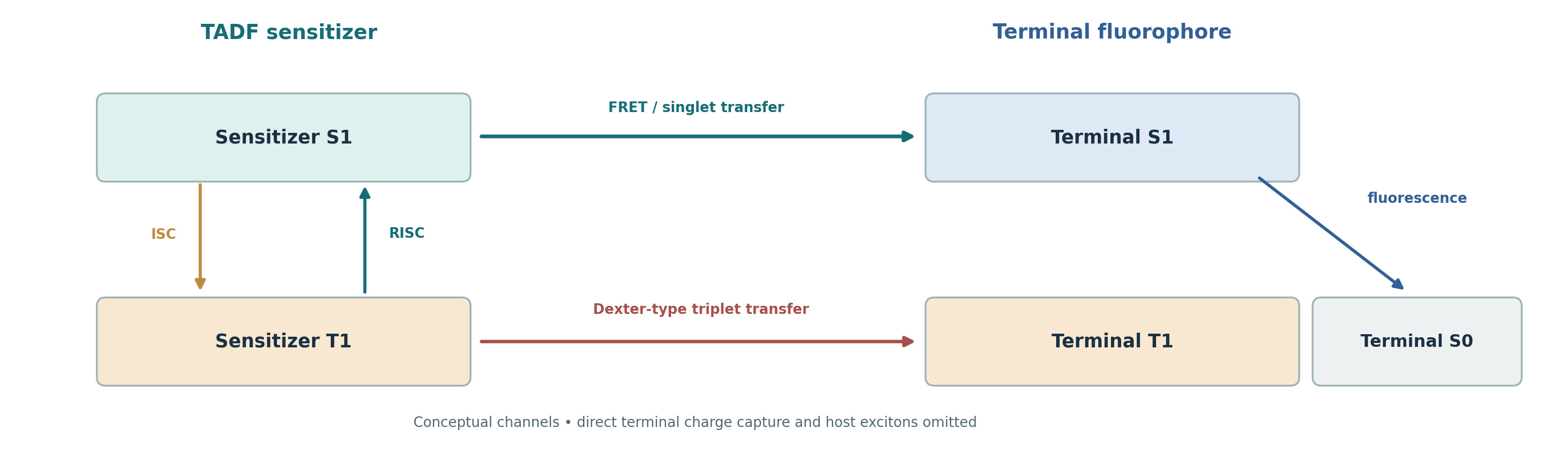
Hyperfluorescence (HF), often called TADF-sensitized fluorescence, separates the triplet-harvesting role from the final photon-emitting role. An electrically excited TADF sensitizer may undergo intersystem crossing (ISC), reverse intersystem crossing (RISC), and singlet-to-singlet transfer to a fluorescent terminal emitter. The latter then emits from its S1 state. This arrangement can retain useful triplet-derived excitation while allowing the terminal dye, rather than the typically broader sensitizer, to define the output spectrum [1, 2].
It is essential to classify the object correctly: the sensitizer can be a conventional donor–acceptor TADF molecule; the terminal dye can be an ordinary fluorescent molecule or an MR emitter; and the complete OLED is an HF architecture. A narrow fluorescent spectrum does not independently establish TADF in the terminal dye, and efficient sensitizer RISC is not a measured terminal-dye RISC rate. Hyperfluorescence does not imply that every transferred excitation becomes an extracted photon.
2. Desired and competing energy-transfer routes
Figure 1 separates the desired sensitizer S1 → terminal S1 Förster resonance energy-transfer (FRET) channel from sensitizer T1 → terminal T1 Dexter-type exchange transfer (DET). Triplet exchange is conditional on the relevant state energies and intermolecular electronic coupling; it is not an unavoidable channel of identical strength for every sensitizer–terminal pair. Terminal fluorescence follows from its S1 population and does not by itself measure sensitizer RISC. Terminal-triplet occupation can introduce quenching or chemical stress, while direct electron or hole trapping on the terminal dye can bypass the intended sensitizer pathway. Additional host excitations, back transfer or interfacial recombination may matter [2, 4].
The idealized 1:3 singlet–triplet spin-statistics argument is a conditional reference for unpolarized recombination, not proof of the actual excitation distribution in a multilayer OLED. Measured device performance must distinguish where charge recombines, which molecule holds the excitation, and which molecule emits the detected photon. Sensitizer residual EL should be quantified rather than assumed zero.
3. FRET, Dexter exchange, and the distance–overlap tradeoff
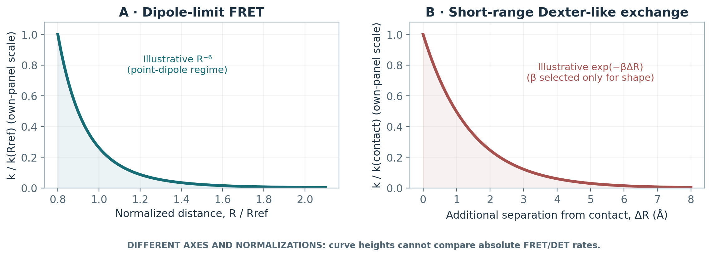
Within the weak-coupling, point-dipole approximation, Förster transfer depends on donor emission–acceptor absorption overlap, transition strengths, refractive environment and dipole orientation, and scales approximately as R⁻⁶ for a fixed donor–acceptor pair. The overlap is sensitizer emission with terminal-emitter absorption, not the distance between two emission maxima. At very short separations, with delocalized excitations or in disordered media, point-dipole and fixed-orientation assumptions may fail. A numerical Förster radius or distance range requires a specified sensitizer, terminal dye and environment [2, 4].
Dexter-type exchange is a short-range electronic-overlap process often represented by an approximately exponential distance dependence. Molecular shielding may reduce triplet exchange, but greater separation may also diminish desired FRET. These channels have different physical prefactors, reference distances, molecular orientation sensitivities and concentration dependence. Therefore, Figure 2 displays independently normalized shapes in separate panels; neither relative curve heights nor a crossover distance can be inferred. The experimentally relevant target is favorable FRET branching while constraining terminal-triplet formation, trapping and aggregation [2, 4].
| Lever | Potential gain | Required independent check |
|---|---|---|
| Strong emission/absorption overlap | More useful sensitizer-S1 to terminal-S1 FRET | Measured overlap; donor PL quenching; prompt-transfer rate |
| Intermediate sensitizer–terminal spacing | Trade off Dexter suppression against FRET reduction | Matched NB-1/NB-3 comparison: PL transfer fits and terminal-triplet TA |
| High terminal-emitter PLQY | Better singlet-to-photon branching | Doped-film PLQY across host and loading |
| Carrier-level engineering | Reduce unintended terminal trapping | Unipolar devices; transient EL; recombination profile |
| Host / optical-stack optimization | Confinement and extraction | Matched stack, angle-resolved EL and J–V–L |
Table 1. Transfer design criteria and their falsification tests.
4. Sensitizer design: fast recovery is not the whole objective
An effective HF sensitizer requires RISC that competes favorably with triplet losses in the actual film, adequate singlet-transfer branching, useful spectral overlap with the terminal absorption band, chemical resilience of both charged and excited states, and acceptable carrier transport. A smaller ΔE_ST can assist thermally activated recovery but cannot on its own specify k_RISC. Local-excitation/charge-transfer mixing, spin–orbit and vibronic coupling, conformation and the dielectric environment matter. Any reported k_RISC should be identified as a model-dependent estimate, not the reciprocal of a measured delayed PL lifetime [2, 3, 5].
Lee et al. reported a complete HF OLED with a quadrupolar DBA-DTMCz sensitizer and 1% ν-DABNA: EQE_max 43.9%, EQE at 1000 cd m⁻² 37.5%, EL peak 473 nm, FWHM 21 nm at 1000 cd m⁻² and CIE (0.12, 0.16) [3, Table 2]. The same original table gives angle-distribution-corrected EQE values of 42.2% (maximum) and 35.9% (1000 cd m⁻²) in parentheses. These optical accounting conventions must not be mixed. Huang et al. separately reported a sensitized deep-blue device with EQE_max 30.8% and LT95 221 h at initial luminance 1000 cd m⁻², metrics of the full device and its stress protocol [5].
5. Terminal-emitter selection and the colour-purity boundary
An HF terminal emitter should possess a strong spin-allowed absorption band overlapping the sensitizer emission, a high useful singlet fluorescence yield, stable color under relevant host/loading/field conditions, suitable frontier-orbital alignment and resistance to aggregation, charge trapping and terminal-triplet accumulation. A multiple-resonance terminal may deliver a narrow spectrum, but MR structure is not synonymous with rapid intrinsic RISC. Narrowband optical PL does not automatically imply equally narrow driven EL; the cavity, orientation, concentration and residual sensitizer emission can affect the observed spectrum [2, 4].
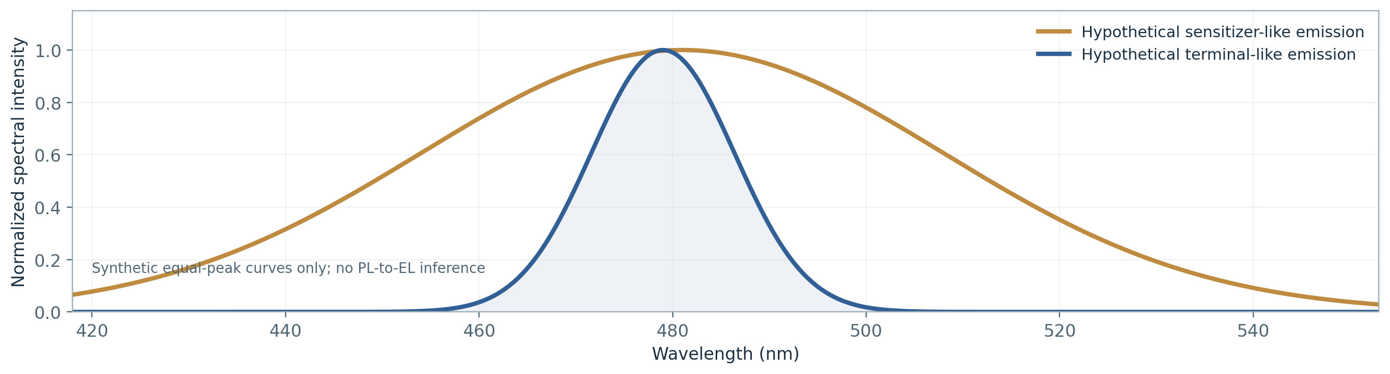
Figure 3 compares synthetic sensitizer-like and terminal-like emission lines within the same hypothetical optical domain, not solution PL against device EL. For measured spectra, report solution/doped-film PL versus driven OLED EL, the wavelength or photon-energy density convention, λ_peak, FWHM units, temperature, loading, drive point and collection geometry. For a narrow feature, ΔE ≈ (hc/λ²)Δλ is a local approximation. Exact conversion of a wavelength spectral density to an energy density requires I_E(E) = I_λ(hc/E) × hc/E² (with consistent units), which can alter both peak and apparent FWHM. Do not convert an EL FWHM into a PL claim.
6. A conservative effective population model
Let S and T denote effective sensitizer singlet and triplet densities; A and U denote terminal-emitter singlet and triplet densities; p is polaron density (all in cm⁻³). G terms have units cm⁻³ s⁻¹. One-body k values, including effective k_FRET and k_DET, have units s⁻¹ for a specified host, loading and environment; k_TTA and k_TPQ have cm³ s⁻¹. All pools share a notional homogeneous-volume convention; in heterogeneous films or across separate spatial regions, transfer terms require suitable spatially resolved or overlap-weighted definitions. This educational model assumes fixed rates and omits explicit host reservoirs, charge transport, back transfer and electric-field dependence:
dS/dt = G_S + k_RISC T + f_S k_TTA T² − (k_r,S + k_nr,S + k_ISC + k_FRET)SdT/dt = G_T + k_ISC S − (k_RISC + k_nr,T + k_DET + k_TPQ p)T − 2 k_TTA T²dA/dt = G_A + k_FRET S − (k_r,A + k_nr,A + k_ISC,A)AdU/dt = G_U + k_DET T + k_ISC,A A − k_loss,U UHere k_TTA T² is the specified triplet-pair encounter-event rate, 2k_TTA T² removes two sensitizer triplets per event, and f_S is the fraction yielding one singlet in the S pool; f_S is neither a delayed-photon yield nor a universal spin-statistical fraction. k_DET T transfers an excitation from sensitizer T to terminal U rather than annihilating it immediately. Loss from U is represented by the lumped k_loss,U U; its channels and products are not resolved here. If the terminal itself exhibits appreciable intrinsic RISC, paired U → A rates and any corresponding back channels must be incorporated rather than assuming terminal triplets are irreversible losses. Effective mixture rates cannot be transferred unchanged between dopings.
For a restricted one-excitation example, impose fixed one-body rates, no TTA, TPQ, back transfer or host reservoir, no direct terminal excitation (G_A = G_U = 0), and terminal ISC as a non-recycling branch. Define a = k_RISC/(k_RISC + k_nr,T + k_DET), f = k_FRET/(k_r,S + k_nr,S + k_ISC + k_FRET), c = k_ISC/(the same sensitizer-S denominator), and q = k_r,A/(k_r,A + k_nr,A + k_ISC,A). The eventual probability of a terminal photon per initial sensitizer triplet is P = afq/(1 − ac), for ac < 1, by summing repeated T → S → T cycles. Hypothetical a = 0.80, f = 0.75, c = 0.15, q = 0.90 give P = 0.54/0.88 ≈ 0.614. A sensitizer photon, if formed instead, is not counted in this terminal-photon quantity. Neither this conditional probability nor f alone is the driven-device EQE; optical outcoupling and electrical excitation generation are excluded.
7. Identifying losses without fitting a preferred cartoon
Competing channels include triplet transfer onto a vulnerable terminal emitter, direct terminal charge capture, sensitizer triplet–polaron and triplet–triplet annihilation, incomplete FRET and residual sensitizer emission, aggregation-induced quenching and excimers, and irreversibly reactive excitons or polarons. Their magnitude is architecture-specific. Sachnik et al. described a single-layer HF architecture in which energetic disorder reduces terminal-dye trapping effects; the authors’ “trap-free” conclusion is not a general theorem for all HF systems [6].
Kinetic claims need complementary experiments: time-resolved and excitation-fluence-dependent PL, host and emitter loading series, temperature series, terminal-triplet-sensitive transient absorption with credible state assignments, single-carrier or carrier-selective device controls, and transient EL. A change in delayed PL alone cannot uniquely identify k_DET. Reversible excitation quenching, altered recombination-zone width and permanent device damage must be distinguished, preferably at matched luminance, current density or inferred exciton loading.
| Observation | Supports | Cannot prove alone |
|---|---|---|
| Delayed terminal PL under sensitizer excitation | Energy routed through a delayed sensitizer population | Unique RISC or absence of TTA/traps |
| Terminal triplet PIA in TA | Population of terminal triplet-like species | Universal Dexter transfer rate without assignments |
| Loading-series EL redshift/broadening | Concentration or environmental sensitivity | A unique molecular aggregate structure |
| Electron-only / hole-only transport | Carrier trapping/balance constraints | Complete OLED degradation kinetics |
| EL lifetime with product analysis | Device ageing and possible chemistry | A molecule-only intrinsic LT |
Table 2. Mechanism-discrimination checklist.
8. Selected primary literature: do not rank unlike devices
Nakanotani et al. reported separate assistant-dopant fluorescent OLEDs across four colors, with publisher-reported EQE_max values of 13.4–18%; these are not matched measurements for one compound [1]. Chan et al. reported a TWO-unit tandem pure-blue HF OLED with EL FWHM 19 nm, EQE 32% at 1000 cd m⁻² and LT95 18 h at initial 1000 cd m⁻² [7]. The formal correction reverses the original Figure 1b legend labels: light-blue is 0.5 wt% ν-DABNA:20 wt% HDT-1:mCBP, and dark-blue is 0.5 wt% ν-DABNA:mCBP [8]. The correction concerns curve assignment; it must not be treated as independent device replication.
Lee et al. reported a DBA-DTMCz/1% ν-DABNA HF OLED with uncorrected EQE_max 43.9% and EQE at 1000 cd m⁻² 37.5%; optical-angle-corrected values in parentheses are 42.2% and 35.9%, respectively. Its EL peak was 473 nm, FWHM 21 nm at 1000 cd m⁻², with CIE (0.12, 0.16) [3, Table 2]. Cho et al. reported distinct matrix-free devices: System A (DMAC-DPS/NB-1) EQE_max 16.4% and EL FWHM 14 nm, and System C (DPAc-DCzBN/NB-2) 21.5% and 15 nm [4]. Huang et al. reported EQE_max 30.8% and LT95 221 h in another sensitized device [5]. These figures cannot be assigned to isolated emitters or pooled across device architectures.
Hua et al. (2024) reported EQE_max 74.5% for a TWO-unit tandem HF OLED [9]; the same primary abstract separately reports a direct single-unit MR-TADF OLED, a different architecture. A tandem architecture can create more than one internal emission event per externally injected charge pair, so a single-emissive-unit probability factorization cannot be applied unaltered. None of these figures constitutes a matched cross-device molecular efficiency ranking. Complete SI stack and lifetime-protocol details remain open wherever not expressly verified.
| Study / architecture | Reported device metric(s) | Interpretive boundary |
|---|---|---|
| Nakanotani 2014; fluorescent terminals | EQE_max 13.4–18% (four colours; separate devices) | Publisher abstract; multiple devices |
| Chan 2021; two-unit tandem HF | EQE@1000 32%; FWHM 19 nm; LT95 18 h @1000 | Two-unit tandem; Figure 1b legend corrected [8] |
| Lee 2023; quadrupolar TADF → ν-DABNA | EQE_max 43.9%; EQE@1000 37.5%; EL 473 nm / 21 nm at 1000; CIE (0.12, 0.16) | Original Table 2; uncorrected values shown; angle-corrected EQE 42.2%/35.9% |
| Cho 2024; matrix-free HF | System A: 16.4%, EL 449 nm/14 nm; System C: 21.5%, EL FWHM 15 nm | Different terminal/host pairs; matched undoped controls 17.0% / 20.3% |
| Huang 2024; sensitized deep blue | EQE_max 30.8%; LT95 221 h at initial 1000 cd m⁻² | Different complete sensitized device; detailed stack SI pending |
| Sachnik 2025; single-layer HF | EQE up to ~25% | Trap-free within tested architecture |
Table 3. Historical primary reports; deliberately not a head-to-head performance ranking.
9. A mechanistic case: encapsulation suppresses triplet leakage
Cho et al. (2024) studied alkylene-strap terminal emitters in matrix-free HF OLEDs. “Matrix-free” means no additional wide-gap inert matrix in the emitting layer: the pristine TADF sensitizer serves as the host, with a small amount of terminal emitter. In System A, DMAC-DPS/1 wt% NB-1 showed EL 449 nm, FWHM 14 nm and EQE_max 16.4%, versus 17.0% for undoped DMAC-DPS. Separately, System C used DPAc-DCzBN/1 wt% NB-2 (EL FWHM 15 nm, EQE_max 21.5%), against its own undoped control (20.3%) [4, Fig. 2; Table 1]. Systems A and C differ in both sensitizer and terminal dye; they are not one matched substitution test.
A more controlled mechanistic comparison doped encapsulated NB-1 and unencapsulated NB-3 into DMAC-DPS at matched loading. From time-resolved PL and the authors’ model, the effective k_DET for NB-1 was 3.2-fold smaller than for NB-3; this is an inferred rate, not direct measurement of an elementary exchange constant. Parameters including k_FRET, Förster radius and mean sensitizer–terminal separation indicated more efficient FRET for unencapsulated NB-3, consistent with closer molecular contact [4, Table 2 and Supplementary Note 5]. Terminal-triplet-assigned photoinduced absorption around 540–560 nm was stronger and longer-lived for NB-3 and reduced for NB-1; transient absorption therefore supplies a complementary mechanistic constraint. Signal assignments, fitted kinetic structure and film conditions limit causal uniqueness. Encapsulation must be optimized for beneficial FRET/DET selectivity, rather than for suppressing Dexter exchange alone. In a minimal single-pass competition, f = k_FRET/(k_FRET + k_r,S + k_nr,S + k_ISC) is the sensitizer-singlet transfer branch, not the full recycled transfer yield.
10. Accounting from sensitizer excitation to external photons
For a single emissive unit and explicit one-excitation accounting boundaries, EQE = γ × Φ_int,eff × η_out is an illustrative photon budget: γ is useful excitation formation per injected electron–hole pair, Φ_int,eff is eventual internal-photon generation per excitation (including ISC/RISC cycles, transfer and terminal emission without double counting), and η_out is the optical extraction fraction for a specified collection convention. Optical-angle correction can change a reported EQE; Lee 2023 publishes both corrected and uncorrected values [3, Table 2]. Residual sensitizer photons, direct terminal charge capture, orientation and field-dependent losses may change together. Tandem architectures need a sum over emissive units or an explicitly defined multi-photon generation term; do not treat their EQE as an isolated-molecule harvesting probability.
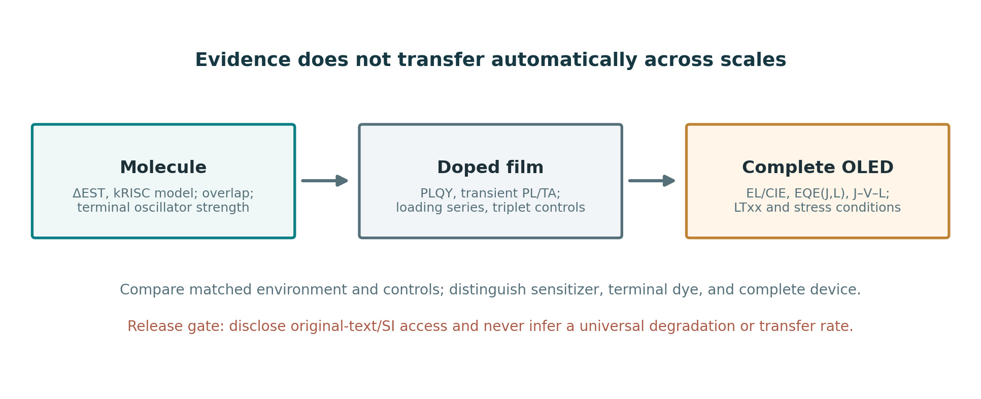
Reporting should separate EQE_max from EQE at specified luminance or current density, alongside EQE–L and EQE–J plots, voltage, roll-off, measured EL bandwidth, CIE, viewing angle and optical correction assumptions. Lee 2023 is a useful matched-row example: 43.9% EQE_max and 37.5% at 1000 cd m⁻² are not interchangeable quantities [3, Table 2]. A high optical PLQY does not independently determine carrier balance or device operational lifetime.
| Group | Minimum required reporting | Failure if omitted |
|---|---|---|
| Materials | Host/sensitizer/terminal identity, concentration, full stack | Mixing unrelated emitter/sensitizer metrics |
| Optics | PL / EL domain; FWHM in nm/eV; CIE, λpeak, angle, drive point | False color-purity comparison |
| Electrical | EQE_max, EQE@L, J–V–L, current density | Roll-off and stack effects concealed |
| Time / degradation | LTxx endpoint, initial brightness, stress mode, temperature, samples | Lifetime claims not comparable |
| Model | Equations, effective rate definitions, model exclusions, fit uncertainty | Effective rates mistaken for elementary rates |
Table 4. Publication-grade device metadata for HF comparisons.
11. Stability, architecture and realistic reporting
High EQE, narrow EL FWHM and short delayed emission times do not independently imply long operational life. Faster RISC can reduce triplet residence under some conditions, but chemical ageing also depends on polaron stability, bond reactivity, exciton density, morphology, interfaces, and charge-transport balance. Reversible exciton–polaron quenching must not be conflated with irreversible bond scission. Publish LT95/LT97/LT50 with initial luminance, drive protocol (constant current or constant brightness), temperature, device area, layer stack and sample count; mismatched lifetime endpoints or stresses cannot support a single-cause stability conclusion [2, 5, 7].
Chan 2021 used a two-unit tandem design, whereas Huang 2024 investigated a different sensitized deep-blue device and considered both spin up-conversion and the resilience of charged/excited species [5, 7]. Sachnik 2025 supplied device-specific evidence for reduced direct terminal charge trapping in a single-layer design, not a claim that all HF stacks are trap-free [6]. Fathima et al. (2026) is a secondary review useful for context, not independent re-measurement of its source devices [10].
12. Open questions, falsifiable experiments and publication boundary
A decisive next study should examine the FRET–Dexter selectivity trade-off rather than optimize either rate in isolation. Prepare matched sensitizer/terminal series with graded peripheral shielding, a constant TADF host, a fixed optical stack and independent variation of guest loading. Constrain singlet transfer through spectral-overlap calculations and prompt PL, terminal-triplet formation through transient absorption, and direct capture through electron-only/hole-only and transient-EL controls. Evaluate device roll-off and stability at explicit common stress conditions. Report fit confidence intervals, sensitivity to alternative rate models and, where possible, film morphology and orientation.
Cross-study benchmarks should lock material identity, mixture fractions, film versus device spectral domain, single-unit versus tandem architecture, full stack, EQE_max, EQE@L, angular correction convention, drive current, CIE, FWHM, lifetime endpoint and stress protocol. Unchecked supporting-information parameters and abstract-only data are explicitly marked unresolved; device metrics are not properties of an isolated sensitizer or terminal emitter. This document was prepared before final owner review. The scientific owner subsequently accepted v3 and authorized public publication on 28 October 2026. GitHub release and live deployment require separate verification.
References
References retain the numbering and DOI data of the owner-accepted Expert Revised v3 manuscript. Evidence access is described in the source disclosure below.
- [1] Nakanotani, H. et al. High-efficiency organic light-emitting diodes with fluorescent emitters. Nature Communications 5, 4016 (2014). DOI: 10.1038/ncomms5016
- [2] Deori, U., Nanda, G. P., Murawski, C. & Rajamalli, P. A perspective on next-generation hyperfluorescent organic light-emitting diodes. Chemical Science 15, 17739–17759 (2024). DOI: 10.1039/D4SC05489J
- [3] Lee, H. et al. Efficient pure blue hyperfluorescence devices utilizing quadrupolar donor-acceptor-donor type of thermally activated delayed fluorescence sensitizers. Nature Communications 14, 419 (2023). DOI: 10.1038/s41467-023-35926-1
- [4] Cho, H.-H. et al. Suppression of Dexter transfer by covalent encapsulation for efficient matrix-free narrowband deep blue hyperfluorescent OLEDs. Nature Materials 23, 519–526 (2024). DOI: 10.1038/s41563-024-01812-4
- [5] Huang, T. et al. Delocalizing electron distribution in thermally activated delayed fluorophors for high-efficiency and long-lifetime blue electroluminescence. Nature Materials 23, 1523–1530 (2024). DOI: 10.1038/s41563-024-02004-w
- [6] Sachnik, O. et al. Pure-blue single-layer organic light-emitting diodes based on trap-free hyperfluorescence. Nature Materials 24, 1742–1748 (2025). DOI: 10.1038/s41563-025-02294-8
- [7] Chan, C.-Y. et al. Stable pure-blue hyperfluorescence organic light-emitting diodes with high-efficiency and narrow emission. Nature Photonics 15, 203–207 (2021). DOI: 10.1038/s41566-020-00745-z
- [8] Chan, C.-Y. et al. Author Correction: Stable pure-blue hyperfluorescence organic light-emitting diodes with high-efficiency and narrow emission. Nature Photonics 15, 245 (2021). DOI: 10.1038/s41566-021-00759-1
- [9] Hua, T. et al. Deep-blue organic light-emitting diodes for ultrahigh-definition displays. Nature Photonics 18, 1161–1169 (2024). DOI: 10.1038/s41566-024-01508-w
- [10] Fathima, A. et al. Molecular design and device engineering of stable blue hyperfluorescent organic light-emitting diodes. Communications Materials 7, 150 (2026). DOI: 10.1038/s43246-026-01196-9
Source access and release boundary
This Expert Revised v3 manuscript retains the companion v2 claim-ledger boundaries and extends them with a Lee 2023 optical-angle-correction distinction, exact FWHM spectral-density convention, and source-conditional kinetic interpretation. Publisher original/main-text entries were checked for Cho 2024, Lee 2023, Chan 2021 correction, Sachnik 2025 and Hua 2024; selected literature metrics remain publisher-abstract level. No complete independent audit of all supplementary device stacks, sample variation, stress conditions or model fit uncertainty has been performed. The four figures remain original conceptual educational illustrations rather than reproduced source graphics. Scientific-owner acceptance and public publication authorization were granted on 28 October 2026, after the manuscript was finalized. This does not establish full primary-source verification.